
Industrial Automation Metal Fabrication — Built for Round-the-Clock Operation
Automation equipment has to index repeatably, assemble at speed and run for years with minimal downtime. The metal parts behind that performance — robot pedestals, conveyor frames, guarding, enclosures — are judged by stiffness, dimensional consistency and how cleanly they fit together on the assembly floor, not by surface cosmetics.
Conwhole has supplied precision metal components for robot systems, conveyor lines, and automated manufacturing cells for over 25 years — all from one Ningbo facility. We cover the processes automation hardware needs: laser cutting of sheet and tube for frames and brackets, CNC machining for robot mounting plates and locating features, press brake forming and stamping for covers and enclosures, and welding by licensed welders for structural frames and guarding assemblies.
What sets us apart for automation clients: one facility for cutting, machining, forming and welding, tolerance discipline that protects fit-up at the cell, documented welding procedures, and full material traceability from mill certificate to finished part.
Key Takeaways:
- Robot pedestals, conveyor frames, guarding and control enclosures — cut, formed, machined and welded in one facility
- Laser sheet cutting up to 6,000 W: 0.5–30 mm carbon steel, 0.5–20 mm stainless, 0.5–15 mm aluminum; tube laser cutting Ø10–160 mm
- CNC machining to ±0.01 mm, with ±0.005 mm on critical bores and datums
- Welded assemblies by licensed welders with documented welding procedures
- One-stop fabrication in Ningbo, China — tube laser, sheet metal, CNC and welding under one roof
- Material grades: structural steel Q235/Q345, stainless 304/316, aluminum 6061/7075
- Prototype to production: laser-cut or machined samples in 7–14 days
- Surface finishing through an audited partner network: powder coating, zinc plating, galvanizing, anodizing
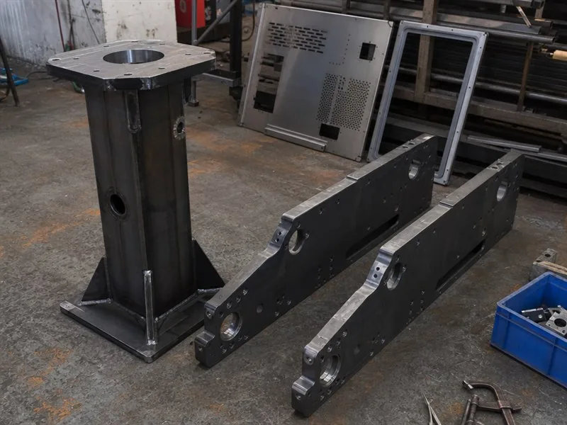
Welding & Frame Assembly for Industrial Automation
Welding by licensed welders for robot pedestals, conveyor frames, machine bases and guarding structures — with documented procedures and dimensional control across the whole assembly.
| Welding Processes | MIG/MAG, TIG, Spot/Projection Welding, Robotic MIG Welding, Stud Welding |
| Welder Qualification | Licensed welders (government-issued welding operation licenses); documented welding procedures with full traceability |
| Materials Welded | Carbon Steel Q235/Q345, Structural Steel, Stainless Steel, Aluminum, Dissimilar Metals |
| Max Component Size | 6,000 × 3,000 × 2,500 mm (length × width × height) |
| Welding Positions | All positions (Flat, Horizontal, Vertical, Overhead) |
| Post-Weld Services | Stress Relief, Weld Inspection (VT, PT, UT, MT), Dimensional Check, Machining |
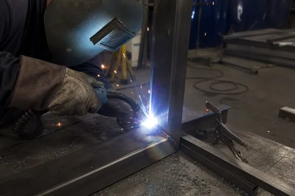
CNC Machining for Automation Components
Precision machining for robot mounting plates, bearing housings, locating blocks, shaft supports and sensor brackets — the interfaces that decide how repeatably a cell indexes.
| Machining Type | 3-, 4- & 5-Axis CNC Milling, CNC Turning, Deep Hole Drilling, Tapping |
| Max Workpiece Size | 1,000 × 500 × 500 mm (Milling), Ø400 × 800 mm (Turning) |
| Tolerance | ±0.01 mm standard, ±0.005 mm on critical bores and datums |
| Surface Finish | Ra 0.8 μm standard, Ra 0.4 μm on fine-finish work |
| Materials Machined | Aluminum 6061/7075, Stainless SUS304/316, Mild Steel, Brass C360, POM, Nylon |
| Inspection | CMM, micrometer, height gauge, bore gauge, go/no-go gauges |
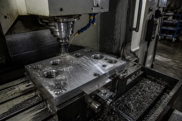
Sheet Metal Fabrication for Automation Frames & Covers
Laser cutting, press brake forming and stamping for frames, covers, panels, brackets and base plates — from one-off prototype sets to repeat production runs.
| Core Processes | Laser Sheet Cutting, Press Brake Bending, Metal Stamping |
| Sheet Thickness | 0.5 – 30 mm carbon steel, 0.5 – 20 mm stainless, 0.5 – 15 mm aluminum (laser, up to 6,000 W); stamping presses 45T – 400T |
| Bending Length | Up to 3,000 mm |
| Part Types | Enclosures, covers, panels, guards, brackets, base plates |
| Tolerance | Laser-cut features ±0.1 mm, formed features ±0.05 mm |
| Volume | Prototype to series production |
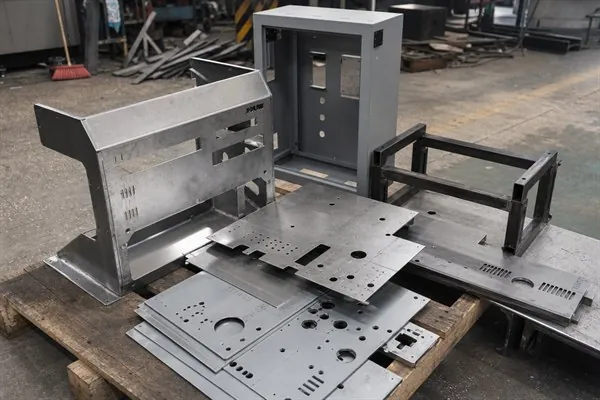
Control Cabinets, Enclosures & Guarding Panels
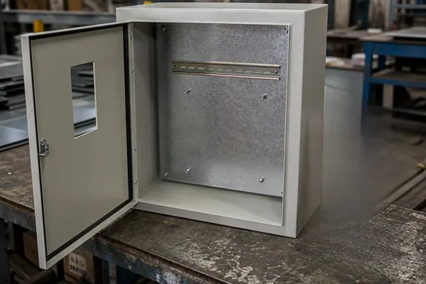
Sheet metal enclosures, mounting plates, DIN-rail supports and guarding panels — supplied as bare metal fabrications for your electrical and safety integrators to populate and wire.
| Core Processes | Laser Sheet Cutting, Press Brake Bending, Welding, Hardware Insertion |
| Enclosure Formats | Wall-mount, floor-standing, double-door, custom sizes to drawing |
| Sheet Thickness | 0.8 – 3 mm typical for cabinet bodies; heavier gauge on request |
| Features | DIN-rail mounting plates, gland plates, hinged doors with viewing windows, gasket channels, welded studs |
| Tolerance | ±0.1 mm on cut and formed enclosure features; door-to-frame gap controlled for gasket seal |
| Finish | Powder coating to RAL, zinc plating, hot-dip galvanizing |
| Scope | Bare metal fabrication only — electrical components, wiring and control assembly are not supplied or installed by Conwhole |
Typical Industrial Automation Parts We Manufacture
| Component Category | Examples | Key Processes |
|---|---|---|
| Robotics & Cobots | Robot base frames, mounting pedestals, welded tube and plate structures, end-of-arm tooling (EOAT) for collaborative robots | Welding, CNC Machining, Tube Laser Cutting |
| Conveyor & Material Handling | Conveyor side frames, crossmembers, drive housings, rollers | Laser Cutting, Welding, CNC Machining |
| Machine Safety & Guarding | Machine guards, safety enclosures, access panels | Sheet Metal Fabrication, Laser Cutting |
| Motion & Positioning | Linear guide rail mounting plates, precision brackets | CNC Machining, Sheet Metal Fabrication |
| Fluid Power | Pneumatic and hydraulic cylinder mounting brackets | CNC Machining, Welding |
| Control & Enclosures | Control cabinet enclosures, DIN rail panels | Sheet Metal Fabrication, CNC Machining |
Why Choose Conwhole for Industrial Automation Metal Parts?
🏗️ One Facility, Four Processes
Laser cutting, CNC machining, press brake forming and welding all from one Ningbo facility. Frames, brackets, plates and enclosures arrive as one matched set instead of four vendor batches with four separate tolerance stacks.
📐 Tolerance Discipline That Protects Fit-Up
±0.01 mm on machined features and ±0.1 mm on laser-cut edges, with CMM inspection on critical datums. Your assembly team gets parts that bolt together without reaming, shimming or hand-fitting at the cell.
📄 Documented Welding & Traceability
Every welded frame is produced under documented welding procedures by licensed welders. Material certificates link each plate back to its mill heat number — the paperwork your end customer’s audit will ask for.
⚙️ DFM Before You Lock the Design
We review drawings for manufacturability before quoting: bend relief, weld access, hole-to-edge distance, tolerance stacking. Catching these at RFQ stage is far cheaper than catching them at first article.
Frequently Asked Questions — Industrial Automation Metal Parts
Q1: What metal parts do you supply for industrial automation equipment?
Robot pedestals and riser columns, conveyor side frames and leg sets, machine bases, perimeter guarding panels, linear guide rail mounting plates, pneumatic and hydraulic cylinder mounting brackets, EOAT brackets and tooling plates, and control cabinet enclosures. Most automation projects combine two or three of these into a single purchase order, which is why cutting, forming, machining and welding all sit in one facility.
Q2: Can you hold the tolerances my cell assembly needs?
Machined features are held to ±0.01 mm, with ±0.005 mm on critical bores and datums. Laser-cut features are held to ±0.1 mm and formed features to ±0.05 mm. Critical datums are verified on a CMM and reported in the inspection record that ships with the batch. If your drawing stacks tolerances across three or four parts in one assembly, send the assembly drawing rather than single parts — we will flag the stack during DFM review.
Q3: Do you fabricate control cabinet enclosures?
We fabricate the sheet metal: cabinet body, door with viewing window, mounting plate, DIN-rail supports, gland plate and welded studs — cut, formed, welded and powder coated to your drawing. We do not supply or install electrical components, wiring contactors or control assembly. Your electrical integrator populates and wires the cabinet; we deliver the bare, finished enclosure.
Q4: What is the typical lead time for automation metal parts?
Laser-cut, tube-cut or machined prototype parts with no tooling: 7–14 days. Press brake prototypes: 7–14 days. Welded frames and enclosures in repeat production: from 15 days depending on finishing. Where new stamping tooling is required, add 4–6 weeks for tool design and manufacture (6–8 weeks for complex progressive dies), with production starting from 15 days after tooling approval.
Q5: Which materials do you work with?
Structural steel Q235/Q345, mild steel, stainless 304/316 and aluminum 6061/7075, plus brass C360, POM and Nylon for machined components. We do not substitute material grades without written approval, and every batch ships with a material certificate linking the finished part back to its mill heat number.
Q6: Can you machine a frame after welding?
Yes, and for automation frames we usually recommend it. Welding distortion moves bore positions and mounting faces, so the sequence is: laser cut, weld, stress relief where required, CNC machine the critical interfaces, then final inspection. Machining after welding is how a pedestal ends up with a mounting face that is actually flat and a bore pattern that actually matches the robot footprint.
Q7: How do you handle surface finishing?
Powder coating to RAL, zinc plating, zinc-nickel plating, hot-dip galvanizing, anodizing for aluminum, wet painting and black oxide — managed through our audited finishing partner network. We match the finish to the operating environment: washdown, coolant exposure, outdoor installation or clean-room.
Q8: How are engineering changes handled once production starts?
Formal ECN route: your change request, our DFM and tooling impact assessment, revised cost and timing, written approval, then implementation. Changes within existing tooling usually take 1–2 weeks; die modification typically runs 3–6 weeks. Every revision is archived against the part number so the drawing on the shop floor always matches the one you approved.