
Industrial equipment demands components that survive continuous vibration, heavy loads, harsh environments, and decades of service life — not the precision cosmetics of consumer goods.
Conwhole has been supplying custom metal components to industrial equipment OEMs for over 25 years. Our capabilities span the full range of industrial machinery fabrication: heavy-duty stamping for structural components, certified welding for machine frames and load-bearing assemblies, CNC machining for precision housings and shaft components, and laser cutting for both prototype development and production runs.
What sets us apart for industrial equipment clients: material grade selection matched to application environment, weld procedure specifications for fatigue-loaded structures, full traceability from mill cert to finished part, and one-stop capability from blanking to surface finishing.
Key Takeaways:
- Heavy press capacity: 63–400 tons for structural components up to 8mm steel
- Welded assemblies certified to AWS D1.1 / ISO 9606-1
- Machined housings for gearboxes, pumps, motors, and fluid handling
- Material grades: structural steel, alloy steel, stainless, aluminum, engineering plastics
- One-stop supplier: stamping + welding + CNC + cutting + finishing
- Prototype to production: tool lead-time 2–6 weeks, FAI in 1–2 weeks
- Industries served: heavy machinery, power & transmission, automation, fluid handling
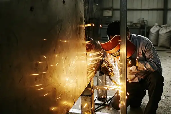
Welding & Assembly for Industrial Equipment
Certified welding for industrial machinery frames, load-bearing structures, and safety-critical assemblies.
| Welding Processes | MIG/MAG, TIG, Spot/Projection Welding, Robot Welding, Stud Welding |
| Welding Standards | AWS D1.1, ISO 9606-1, ISO 15614-1, ASME IX |
| Materials Welded | Carbon Steel, Structural Steel, Stainless Steel, Aluminum, Dissimilar Metals |
| Max Component Size | 6,000 × 3,000 × 2,500 mm (Large machinery frames) |
| Welding Positions | All positions (Flat, Horizontal, Vertical, Overhead) |
| Post-Weld Services | Stress Relief, Weld Inspection (VT, PT, UT, MT), Dimensional Check, Machining |
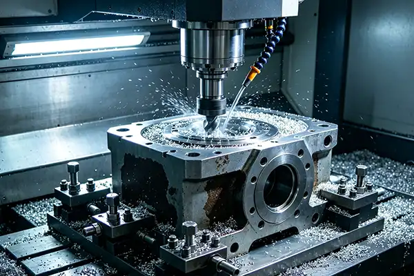
CNC Machining for Industrial Equipment
Precision machining for housings, shafts, flanges, brackets, and functional interfaces used in industrial machinery.
| Machining Type | 3-Axis & 4-Axis CNC Milling, CNC Turning, Deep Hole Drilling, Tapping |
| Max Workpiece Size | 1,200 × 800 × 600 mm (Milling), Ø500 × 1,000 mm (Turning) |
| Tolerance | ±0.01 mm standard, ±0.005 mm on critical bores and datums |
| Surface Finish | Ra 1.6 – Ra 3.2 μm standard, finer finish available on request |
| Materials Machined | Carbon Steel, Alloy Steel, Stainless Steel, Aluminum, Cast Iron |
| Inspection | CMM, micrometer, height gauge, bore gauge, go/no-go gauges |
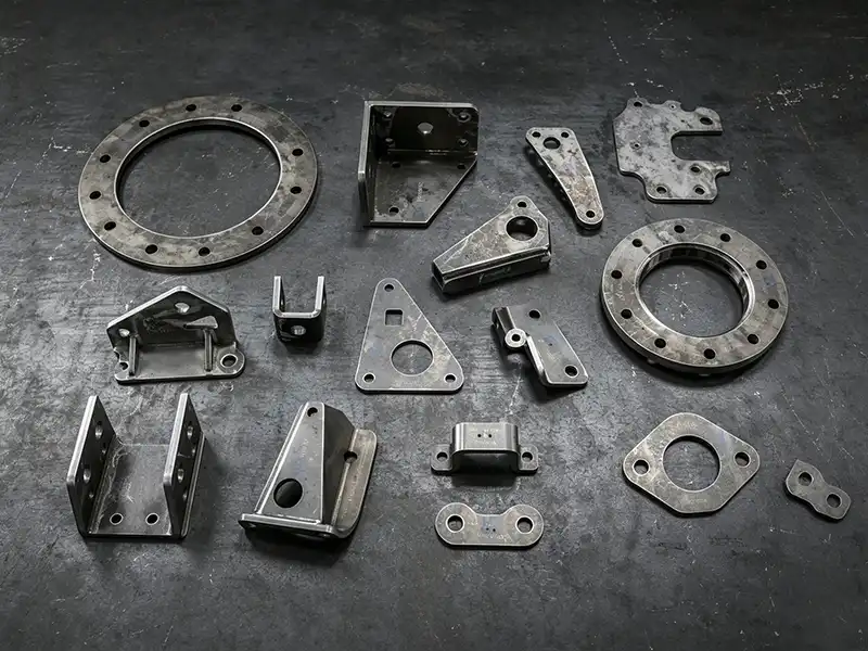
Sheet Metal Fabrication for Industrial Equipment
Fast-turn sheet metal fabrication for prototype development and production manufacturing.
| Core Processes | Laser Sheet Cutting, Metal Stamping, Press Brake Bending |
| Sheet Thickness | 0.5 – 30 mm (Steel), 0.5 – 20 mm (Stainless), 0.5 – 15 mm (Aluminum) |
| Part Types | Enclosures, covers, panels, guards, brackets, base plates |
| Tolerance | ±0.1 mm on cut features, ±0.05 mm on formed features |
| Finishes | Powder coating, zinc plating, galvanizing, paint, anodizing |
| Volume | Prototype to series production |
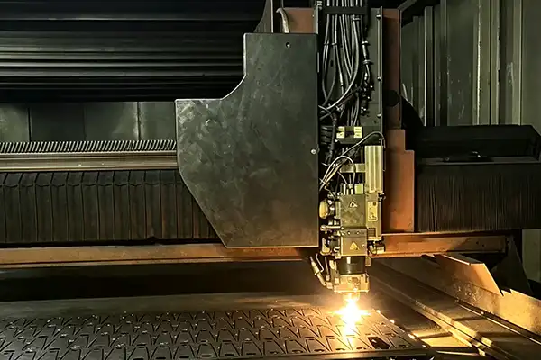
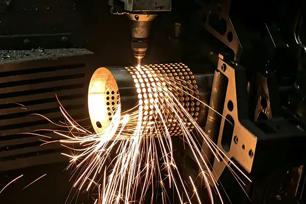
Tube / Round-Part Special Fabrication for Industrial Equipment
For cylindrical covers, end caps, ducts, and special round components used in machinery and air-handling systems.
| Core Processes | Tube Laser Cutting, Metal Spinning |
| Tube/Profile Max Size | Ø350 mm round, 300×300 mm square, 250 mm channel |
| Profile Max Length | 6,000 mm |
| Applicable Parts | Round housings, end caps, fan covers, duct components, formed covers |
| Tolerance | ±0.1 mm |
| Use Case | Special-shaped parts, low-volume runs, visual covers |
Typical Industrial Equipment Parts We Manufacture
| Component Category | Examples | Key Processes |
|---|---|---|
| Heavy Machinery & OEM | Machine bases, structural frames, side panels, equipment feet, mounting brackets, lifting lugs | Welding, CNC Machining, Sheet Metal Fabrication |
| Power Transmission | Gearbox housings, motor frames, mounting flanges, coupling guards, drive pulleys, shaft supports | CNC Machining, Welding, Sheet Metal Fabrication |
| Automation & Robotics | Robot pedestals, sensor mounting brackets, cable carrier supports, control panel enclosures, pneumatic manifolds | Welding, CNC Machining, Sheet Metal Fabrication |
| Fluid Handling & Processing | Pump housings, valve bodies, filter housings, heat exchanger plates, pipe fittings, tank ends | CNC Machining, Welding, Sheet Metal Fabrication |
| Electrical & Control | Control cabinet chassis, terminal block brackets, DIN rail clips, switchgear components, panel-mount frames | Sheet Metal Fabrication, CNC Machining |
| Structural & Support | Equipment guard frames, access platforms, equipment skids, hand-rail brackets, mounting channels | Welding, Sheet Metal Fabrication, Tube/Round-Part Fabrication |
Why Choose Conwhole for Industrial Equipment Metal Parts?
🏗️ Heavy-Duty Fabrication Capability
Press capacity up to 400 tons and welding work envelope up to 6m × 3m × 2.5m — we handle the components that smaller fabrication shops turn down. Heavy machinery frames, thick plate weldments, and large CNC housings are our regular work.
📐 Application-Engineered Material Selection
We don’t just quote what you specify — we recommend material grades based on load, fatigue, environment, and cost. Need to upgrade from Q235 to Q345 for a load-bearing frame? We flag it during DFM review and explain the trade-offs.
🔩 Certified Weld Procedure & Traceability
Every welded assembly comes with WPS (Weld Procedure Specification) documentation. Material certificates link every steel plate back to its mill heat number. For load-bearing structures, this documentation is the difference between OEM-grade and disaster.
⚙️ One-Stop From Blanking to Finished Sub-Assembly
Stamping + welding + CNC + cutting + finishing in one facility. You supply drawings, we deliver machined, coated, ready-to-install sub-assemblies. No coordinating 3-4 suppliers. No shipping work-in-process between shops. No handoff quality gaps.
Frequently Asked Questions — Industrial Equipment Metal Parts
Q1: What is the maximum size of welded assembly you can produce?
Our largest robotic welding work envelope is 6,000 × 3,000 × 2,500 mm (length × width × height), with single-piece weights up to 5 tons. For larger structures, we deliver sub-assemblies with field-weldable joints and matching WPS documentation. We routinely produce heavy equipment frames, machine bases, and large structural weldments within these limits.
Q2: Can you guarantee material grade matching and full material traceability?
Yes. We do not substitute material grades without explicit written approval. Every batch ships with a Mill Test Certificate (MTC) that links the finished part to the original steel heat number, batch, and chemical composition. For critical structural applications, we provide full traceability documentation aligned with EN 10204 3.1 standard. If we ever suggest a substitution, it’s during DFM review with full cost/performance justification.
Q3: Are WPS and PQR welding procedure documents available?
Yes. Every welded assembly is produced under a documented WPS with corresponding PQR (Procedure Qualification Record). Our welders are certified to AWS D1.1 and ISO 9606-1. For projects requiring ASME Section IX certification, we can work with your third-party inspector to validate weld procedures and operator qualifications. We’re happy to share sample WPS documentation during RFQ stage.
Q4: What is your typical production lead time for industrial metal components?
Lead time depends on whether tooling is required. For laser-cut or machined prototypes (no tooling): 1-2 weeks. For stamped parts with new tooling: tool design + manufacturing = 4-6 weeks, plus 1-2 weeks for first samples and FAI, plus 1-2 weeks for PPAP if required. Total typical: 4-10 weeks. We offer rush programs for prototypes and NPI phases — talk to us about your project timeline.
Q5: Can you perform thick plate welding over 10mm thickness?
Yes. Our robotic MIG welding cells are configured for thick plate work up to 25mm in single-pass or multi-pass configurations. For heavy structural steel (Q345, Q390, A572 Grade 50), we use preheat and interpass temperature control per AWS D1.1 requirements. We also offer SAW (Submerged Arc Welding) for very thick plate applications through partner network — talk to us about your specific thickness and joint configuration.
Q6: Do you provide full complete mechanical assembly service?
Yes. We deliver sub-assemblies and complete mechanical assemblies — including purchased component sourcing (bearings, fasteners, motors, gearboxes per your BOM), in-house manufactured components (frames, brackets, housings), final assembly, alignment, and testing. We can act as your complete mechanical sub-assembly supplier under a single PO, simplifying your vendor management.
Q7: What kinds of surface treatments can you supply?
We offer shot blasting, powder coating, hot-dip galvanizing, zinc plating, zinc-nickel plating, anodizing (for aluminum), wet painting, and black oxide — through our own paint line and managed finishing partner network. We match the surface treatment to your operating environment: salt-spray requirements, UV exposure, chemical contact, or temperature resistance.
Q8: How are engineering changes (ECN) managed during mass production?
We follow a formal Engineering Change Notice (ECN) process: your ECN request → our DFM and tooling impact assessment → revised tooling cost (if any) and timeline → written approval → implementation. For minor changes within existing tooling, we implement in 1-2 weeks. For changes requiring tooling modification, lead time depends on scope (typically 3-6 weeks for die modifications; up to 12 weeks for new tooling). All ECN changes are documented and archived for traceability.