
Design for Manufacturability (DFM) Services
Optimize your custom metal components before production — our mechanical engineering team performs comprehensive 3D CAD DFM analysis to eliminate manufacturing bottlenecks, reduce unit cost, and guarantee seamless fabrication quality.
Engineering DFM Analysis & Value Engineering Optimization
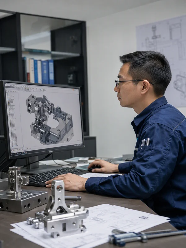
Submitting unoptimized 3D CAD designs directly to fabrication often results in hidden manufacturing costs, tool access conflicts, excessive machining setup times, or unexpected part warping during welding and bending. At Conwhole, we believe great custom metal parts start with rigorous engineering review.
Our Design for Manufacturability (DFM) and Value Engineering service bridges the gap between your original design concept and efficient shop-floor production. By conducting thorough geometric, tolerance, and material evaluations prior to tooling or chip-making, we help OEM buyers achieve 15% to 30% unit cost reductions while accelerating time-to-market.
Key Takeaways
- Free Engineering DFM Report: Comprehensive 3D CAD manufacturability review provided with every RFQ submission.
- Tolerance Stack-Up Resolution: Re-evaluating over-specified tolerances to optimize CNC machine toolpaths and bending setups.
- Material & Process Optimization: Recommending standard stock sizes and optimal metalworking methods to eliminate scrap.
- Strict IP & NDA Confidentiality: Encrypted file storage with non-disclosure agreement (NDA) protection for all client drawings.
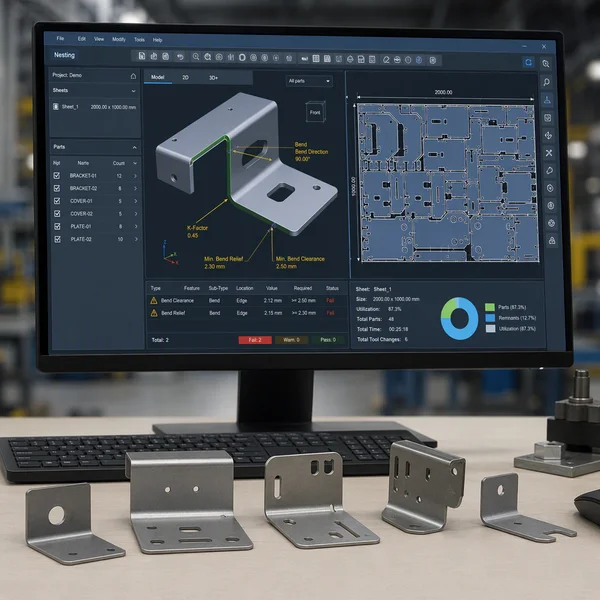
Sheet Metal Bending & Laser Cutting DFM
We evaluate sheet metal CAD models to prevent hole-to-bend distortion, ensure standard press brake tooling clearance, and optimize nesting layouts on laser bed sheets to maximize material utilization.
| Parameter / Capability | Technical Specification |
|---|---|
| Bending Rule Audit | Minimum bend radius (1T rule), bend relief slot verification, hole-to-bend distance (≥ 3T + R) |
| Laser Nesting Check | Common-line laser cutting optimization, minimum web distance between cutouts (≥ 2× sheet thickness) |
| Tooling Clearance | Flange length vs standard punch/die access checks to eliminate custom tooling costs |
| Material Standardization | Matching standard gauge thickness (1.0 mm, 1.5 mm, 2.0 mm, 3.0 mm) to reduce material lead times |
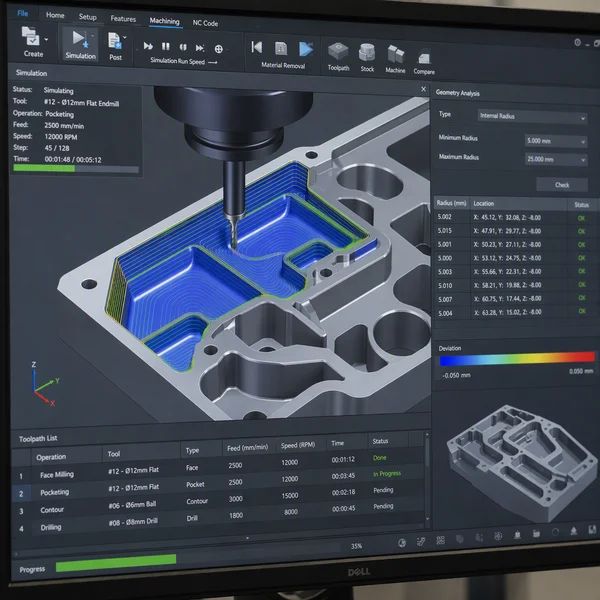
Precision CNC Machining DFM Optimization
We analyze machined prismatic and cylindrical parts to minimize setup changes, avoid deep narrow pockets that cause tool chatter, and standardize corner radii for high-speed CNC milling cutters.
| Parameter / Capability | Technical Specification |
|---|---|
| Internal Radius Check | Replacing sharp internal corners with cutter-friendly radii (R ≥ 1/3 pocket depth) |
| Pocket Depth-to-Width | Keeping pocket depth within 4× tool diameter to prevent tool deflection and chatter |
| Setup Minimization | Designing features accessible from 1 or 2 fixture setups (reducing 5-axis indexing time) |
| Tolerance Rationalization | Designating non-critical features to ISO 2768-m, reserving ±0.01 mm for critical datum faces |
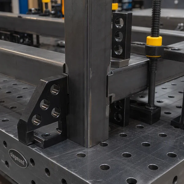
Welded Assembly & Fixture Alignment DFM
For multi-part welded structures, we optimize joint access, recommend self-locating tab-and-slot alignments, and strategic stitch welding sequences to prevent thermal warping.
| Parameter / Capability | Technical Specification |
|---|---|
| Tab-and-Slot Design | Implementing laser-cut interlocking tabs to eliminate expensive assembly jigs |
| Joint Accessibility | Verifying torch angle access for TIG/MIG welding gun head clearance |
| Warping Mitigation | Recommending balanced weld placement and post-weld stress relief (PWHT) callouts |
| Hardware Integration | Standardizing press-fit PEM hardware, helicoils, and clearance hole patterns |
Value Engineering Cost Reduction Analysis
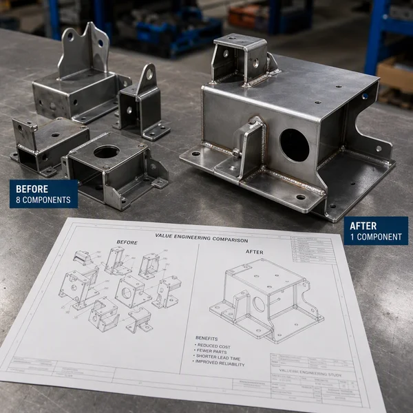
Our engineering team conducts cost-breakdown audits on complex hardware assemblies, identifying opportunities to consolidate multiple machined parts into single bent sheet metal weldments or vice versa.
| Parameter / Capability | Technical Specification |
|---|---|
| Part Consolidation | Merging multi-piece bolted brackets into single laser-cut and bent components |
| Process Conversion | Transitioning low-volume CNC machined parts to laser/press brake fabrication when appropriate |
| Cost Savings Target | Average 15% to 30% piece-part cost reduction achieved per optimized assembly |
| CAD Turnaround | Updated STEP / DXF files and full DFM report provided within 24 to 48 hours |
Representative DFM Optimization Case Studies
| Component Type | Original Design Issue | Conwhole DFM Solution | Impact & Result |
|---|---|---|---|
| Industrial Chassis | 8 separate CNC milled bracket plates bolted together | Consolidated into 2 laser-cut & bent sheet metal parts with tab-and-slot welding | 35% Cost Reduction, assembly time cut from 2 hrs to 20 mins |
| Medical Enclosure | Deep internal pocket with sharp 90° corners (R0.5) requiring EDM | Increased internal radius to R3.0 mm for high-speed end mill processing | 50% Machining Time Saved, eliminated expensive sinker EDM process |
| Automotive Base | Holes placed too close to sheet metal bend line, causing hole ovality | Added bend relief cutouts and shifted hole positions by 1.5 mm | 100% Hole Concentricity, zero secondary reaming required |
| Server Cabinet | Non-standard 1.8 mm aluminum plate requiring custom sheet order | Standardized design to 2.0 mm 5052-H32 stock sheet with minor CAD scaling | Lead Time Reduced by 2 Weeks, raw material unit cost dropped 18% |
| Marine Sensor Frame | Heavy multi-pass weld seam causing 3 mm frame distortion | Redesigned weld joint sequence and added 3D modular clamping fixtures | Warping Reduced to <0.3 mm, eliminated post-weld hydraulic straightening |
Why Choose Conwhole for DFM Engineering Services?
Experienced Mechanical Engineering Team
Our senior CAD/CAM engineers have decades of hands-on shop floor experience across CNC machining, sheet metal bending, and robotic welding, giving you practical, actionable advice.
Measurable Unit Cost Reductions
We actively identify over-toleranced features, non-standard stock sizes, and complex machining operations to deliver an average of 15% to 30% cost savings on your production orders.
Tab-and-Slot Self-Aligning Design Options
We introduce laser-cut interlocking tabs and slots for welded frame assemblies, drastically lowering fixture setup costs and eliminating assembly alignment errors.
Strict Non-Disclosure & IP Security
Your proprietary 3D CAD files and drawing intellectual property are protected under binding Non-Disclosure Agreements (NDAs) and stored on secure, encrypted internal servers.
Q1: What CAD drawing file formats do you require for a DFM review?
We prefer 3D CAD solid models in STEP (.stp, .step) or IGES (.igs) format, alongside SolidWorks native files (.sldprt, .sldasm). 2D vector files in DXF or DWG format and PDF engineering drawings with explicit tolerance notes are also recommended.
Q2: Is the DFM analysis service free of charge?
Yes. Conwhole provides complimentary preliminary DFM reviews for all custom metal component quotation requests. Our goal is to ensure your design is 100% production-ready before order placement.
Q3: How long does a typical DFM analysis report take?
For standard custom parts and sub-assemblies, our engineering team completes the DFM evaluation and provides annotated CAD feedback alongside your quotation within 24 to 48 hours.
Q4: Will Conwhole modify my CAD drawings directly without permission?
No. We never alter your original CAD models without explicit authorization. We provide clear 3D PDF markups and proposed STEP revision files for your engineering team to review, test, and approve.
Q5: What are the most common DFM mistakes in sheet metal design?
The most frequent issues include placing holes too close to bend lines (< 3T distance), specifying internal bend radii smaller than material thickness, and calling out non-standard sheet metal gauge thicknesses that require custom mill runs.
Q6: How does DFM analysis reduce CNC machining costs?
By standardizing internal corner radii to fit standard end mills, reducing pocket depths, and designing features accessible in 1 or 2 fixture setups, DFM reduces machining time and eliminates custom tooling requirements.
Q7: How do you protect client IP and proprietary drawing designs?
We sign Non-Disclosure Agreements (NDAs) before reviewing any confidential design files. All customer data is archived on encrypted servers with strict internal staff access controls.
Q8: Can Conwhole fabricate prototypes after DFM approval?
Yes. Once the optimized DFM design is approved, we rapidly transition into prototype fabrication, delivering physical samples in as fast as 5 to 7 business days for physical testing and validation.