
10 MIN READ
Sheet Metal DFM Guide: Bending Radius, Hole Clearance & Relief Cuts
Master essential Design for Manufacturing (DFM) rules for custom sheet metal parts. Learn minimum bend radius requirements, hole-to-bend distance formulas, relief cut standards, and bend allowance calculations to eliminate scrap and reduce tooling costs.
•
Verified for ISO 2768-m Precision Standards
Key Takeaways for Procurement & Engineering Teams
- Minimum Bend Radius Rule ($R_$): Never specify an inside bend radius smaller than sheet thickness ($R ge 1.0t$) for carbon steel and stainless steel, or $R ge 1.5t–2.0t$ for hard aluminum alloys, preventing material tensile fracture.
- Hole Distortion Prevention ($D_$): Holes positioned too close to a bend line experience severe elliptical stretching during air bending. Always maintain an edge-to-bend line clearance of at least $2.5t + R$.
- Bend Relief Cut Standard: When bending adjacent tabs, uncontrolled tearing occurs at the corner intersections. Implement rectangular or teardrop relief cuts with width $ge 1.5t$ and depth extending past the bend tangent line.
- Cost Optimization Impact: Following standard press brake tooling guidelines eliminates custom die setup fees, lowers scrap rates by ~15%, and ensures seamless prototype-to-production scalability.
Why Design for Manufacturing (DFM) Matters in Sheet Metal
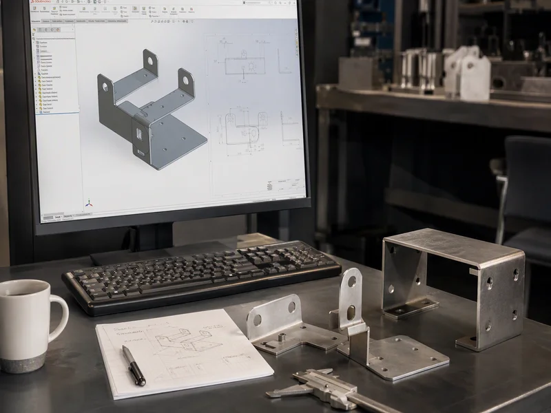
In custom sheet metal fabrication, up to 80% of part manufacturing costs and quality defects are determined during the 3D CAD design phase. While modern fiber laser cutters and multi-axis CNC press brakes offer immense flexibility, physical metal deformation is governed by strict metallurgical limits.
Ignoring basic geometric constraints—such as placing mounting holes on a bend line or specifying an impossibly sharp inside corner—forces fabricators to perform secondary machining, build expensive custom tooling, or scrap deformed parts. This guide outlines the exact geometric rules Conwhole engineers use to audit customer drawings before production.
1. Minimum Inside Bend Radius ($R_$) Standards
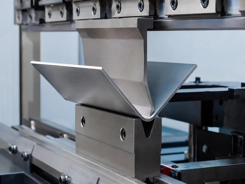
When sheet metal is bent on a CNC press brake, the outer surface undergoes severe tensile strain while the inner surface compresses. If the inside bend radius ($R$) is specified too sharp, the material tensile limit is exceeded, resulting in outer surface orange-peeling, micro-cracking, or complete fracture.
Material-Specific Minimum Bend Radius Rules
The minimum inside radius depends directly on material elongation and yield strength:
- Mild Steel (SPCC / Q235 / A36): $R_ = 1.0t$ (Ductile material handles tight air bending easily).
- Stainless Steel (304 / 316): $R_ = 1.0t$ to $1.25t$ (Higher work-hardening rate requires slightly larger punch radius).
- Aluminum (Al 5052-H32): $R_ = 1.0t$ (Excellent cold formability).
- Aluminum (Al 6061-T6): $R_ = 1.5t$ to $2.0t$ (T6 temper is prone to snapping if bent sharper than $1.5t$).
Pro DFM Tip — Universal Tooling Economy: Always aim to match your drawing's inside bend radius to standard press brake punch nose radii (e.g., $R = 0.8text$, $1.0text$, $1.5text$, or $2.0text$). Specifying non-standard radii (like $R = 1.13text$) forces special tool grinding or costly custom die setups without providing functional benefit.
2. Hole-to-Bend Distance & Bend Relief Cut Standards
Placing holes, slots, or cutouts too close to a bend line is one of the most frequent sheet metal design errors. During press brake air bending, the plastic deformation zone extends beyond the immediate bend tangent line. If a hole enters this deformation zone, the material stretches unequally, causing severe elliptical hole distortion and thread misalignment.
The $2.5t + R$ Clearance Formula
To ensure holes remain perfectly round after bending, the minimum distance ($D$) from the edge of the hole to the bend line must satisfy:
Where $t$ = sheet thickness, and $R$ = inside bend radius. For critical tapped holes or bearing press-fits, increase safety margin to $D_ ge 3.0t + R$.
Bend Relief Cut Rules for Flanges & Tabs
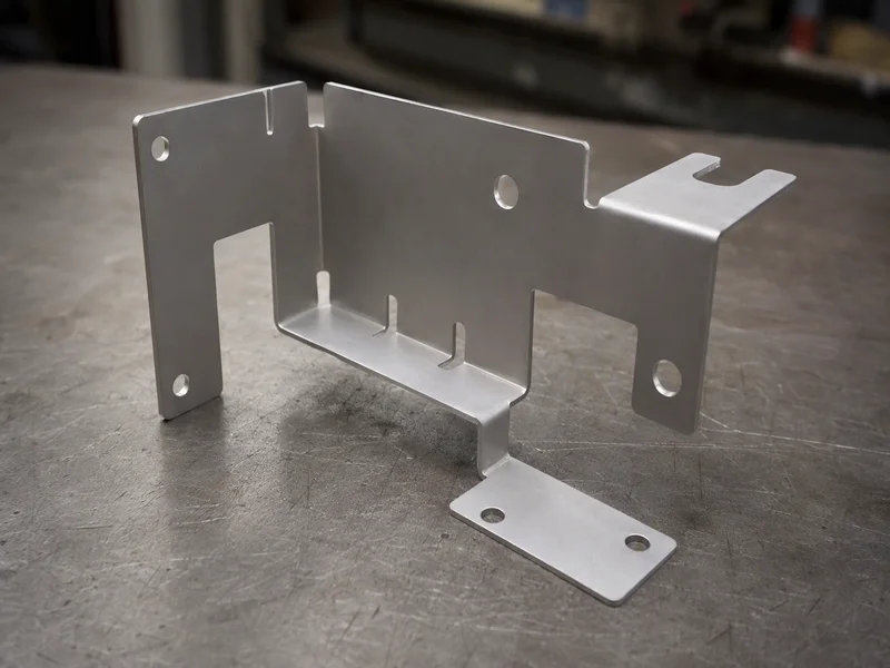
When a partial flange or tab is bent adjacent to flat sheet metal, intense tearing stresses accumulate at the inside corners. Without proper relief cutouts, the sheet metal will tear unpredictably, creating sharp burrs and structural weaknesses.
Rectangular Relief Cut
Width ($W$) $ge 1.5t$ (or min $1.5text$). Depth ($D_r$) must extend past the bend tangent line by $D_r ge R + 1.0t$. Best for standard laser-cut sheet metal.
Teardrop / Circular Relief
Diameter $ge 1.5t + R$. Eliminates sharp stress concentration corners, ideal for aerospace or high-vibration hardware enclosures.
3. Comprehensive Sheet Metal DFM Matrix & Bend Allowance Formulas
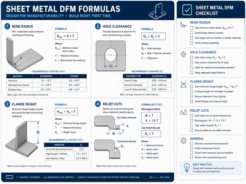
To calculate flat pattern laser blank sizes accurately, engineers use the K-Factor (ratio of neutral axis position to sheet thickness). Below is the comprehensive technical reference matrix combining material parameters, minimum clearances, and K-Factor values for custom fabrication.
| Sheet Metal Feature | Minimum Absolute Limit | Recommended DFM Standard | K-Factor Range (Air Bend) |
|---|---|---|---|
| Inside Bend Radius ($R$) | $1.0t$ (Steel/SS), $1.5t$ (Al) | Match standard press punch ($R = 1.0–2.0text$) | $0.33 – 0.38$ (Steel) |
| Hole to Bend Distance ($D$) | $2.5t + R$ | $3.0t + R$ (or relief slot before bend) | $0.40 – 0.45$ (SS 304) |
| Bend Relief Width ($W$) | $1.5t$ (Min $1.5text$) | $2.0t$ (Extending past bend line) | $0.33 – 0.40$ (Al 5052) |
| Flange Minimum Height ($H$) | $4.0t + R$ | $5.0t$ (To fully span V-die shoulders) | N/A |
| Internal Cutout to Sheet Edge | $2.0t$ | $2.5t$ (Prevents laser distortion) | N/A |
Rapid 24-Hour DFM Audit
Our senior sheet metal engineers review your STEP/CAD files within 24 hours, identifying bend line conflicts, hole distortions, and radius optimization opportunities before cutting metal.
Multi-Axis CNC Precision Bending
Equipped with high-precision CNC press brakes featuring automatic crowning and 6-axis backgauges, ensuring angular accuracy within ±0.3° and linear tolerances meeting ISO 2768-m.
Prototype to Volume Scalability
Seamlessly transition from quick-turn prototypes (1–50 pcs) using flexible laser cutting and bending, to automated progressive stamping dies for high-volume cost reduction.
Integrated Surface Finishing
From powder coating and anodizing to zinc plating and electropolishing, Conwhole manages full end-to-end hardware finishing with CMM inspection and salt spray testing reports.
Q1: What happens if I specify an inside bend radius smaller than sheet metal thickness ($R < 1.0t$)?
Specifying $R < 1.0t$ causes excessive outer tensile stress during press brake bending, leading to visible surface cracking, weakened structural strength, or tool nose indentation marks. For ductile mild steel, a sharp punch can crease the metal, but for stainless steel or hard aluminum (6061-T6), it risks complete material fracture.
Q2: How can I fix a hole that must be placed closer to a bend line than $2.5t + R$?
If product space constraints force a hole within $D < 2.5t + R$, you can: (1) Add a rectangular or teardrop relief slot cutting across the bend tangent line before bending, (2) Ream or drill the hole in a secondary CNC machining operation after press brake bending, or (3) Use a custom press brake rocker die setup.
Q3: Why are relief cuts necessary when bending adjacent flange tabs?
Without relief cuts, the tearing stresses generated at the intersection between the bent tab and the flat sheet cause uncontrolled material tearing, metal bulging, and edge distortion. Laser-cutting rectangular or teardrop relief slots ($ge 1.5t$ wide) isolates the bend deformation zone and creates clean $90^circ$ corners.
Q4: What is the minimum flange height required for press brake bending?
The minimum flange height must be at least $4.0t + R$ (preferably $5.0t$) so the sheet metal can span across the press brake bottom V-die shoulders during air bending. Flanges shorter than $4.0t$ slip into the V-groove, resulting in severe bend angle inaccuracy or impossible bending.
Q5: What K-Factor should I use in SolidWorks / Inventor for sheet metal flat pattern calculation?
For standard press brake air bending with universal V-dies, use $K = 0.33$ to $0.38$ for mild steel, $K = 0.40$ to $0.45$ for stainless steel 304, and $K = 0.33$ to $0.40$ for aluminum 5052. Conwhole's CAD software automatically applies exact empirical bend deduction tables based on our press brake tooling.
Q6: Does laser cutting affect hole tolerance before sheet metal bending?
Modern fiber laser cutting holds hole positional tolerances within $pm 0.1text$. However, if a hole is placed too close to a laser-cut outer edge ($< 2.0t$), thermal expansion during laser cutting can distort the narrow metal bridge. Maintaining $ge 2.0t$ edge distance preserves hole roundness.
Q7: Can Conwhole perform DFM checks directly on STEP or IGES files?
Yes. Conwhole's engineering team accepts 3D STEP, IGES, SolidWorks (.sldprt), and 2D DXF/DWG drawings. We run automated DFM feature checks and provide a detailed PDF feedback report showing optimized bend radii, hole clearances, and cost-saving recommendations within 24 hours.
Q8: How does proper DFM design reduce custom sheet metal part unit cost?
Proper DFM design allows parts to be manufactured using standard universal press brake tooling and automated fiber laser nesting. It eliminates secondary CNC drilling, manual burr grinding, and custom die grinding fees—reducing total part cost by 15% to 30% and cutting production lead times in half.
Need Professional DFM Feedback on Your Sheet Metal Hardware Drawing?
Send your STEP/CAD files to Conwhole engineering team. We will evaluate bend radii, hole clearances, and relief cut parameters—providing a comprehensive 24-hour DFM audit report and competitive quote.