
Laser Cutting Tolerances: A Practical Guide for OEM Buyers
What fiber laser cutting actually holds — the standard ±0.1 mm cut tolerance, what ±0.05 mm really measures, how material and wall thickness move the practical limit, and how to dimension a drawing so your quote is accurate.
Key Takeaways for Procurement & Engineering Teams
1. Standard tolerance: Fiber laser cutting delivers ±0.1 mm cut-to-length / profile accuracy and ±0.05 mm positioning accuracy for most tube and sheet profiles.
2. Material matters: Mild steel and stainless hold tighter tolerances than aluminum and copper. For aluminum tube, ±0.15 mm is the practical standard.
3. Feature rules: On tube, minimum hole diameter is 1.2 × material thickness and minimum slot width equals material thickness. Dimension holes from the tube end, not a floating reference.
4. Drawings drive quotes: Specify tube OD and wall thickness separately, mark only the dimensions that matter, and supply 3D STEP files for compound angle cuts to get an accurate quote.
On this page
1. Standard tolerances → 2. Sheet vs tube → 3. Material & thickness → 4. Drawing specs → 5. FAQ →
When you source laser-cut metal parts, the tolerance you write on the drawing decides both the fit and the price. Over-specify beyond what the process naturally delivers and you pay for secondary operations you do not need; under-specify and the parts arrive with gaps that fail at assembly, long after the tooling is paid for.
At Conwhole, fiber laser cutting — for both sheet and tube — is an in-house capability. The figures in this guide are the same values our engineers use during DFM review, published so you can quote against them with confidence rather than guessing at a supplier’s real capability.
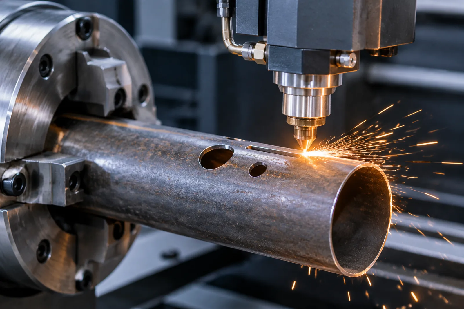
Fiber laser cutting head cutting precise holes in a steel tube — kerf width and hole roundness are what the tolerance table below is really describing.
Standard Tolerances for Fiber Laser Cutting
These are the baseline figures for our in-house fiber laser cells. Treat them as the default expectation for a normal production drawing — no special agreement, no secondary machining.
| Parameter | Standard tolerance | What it governs |
|---|---|---|
| Positioning accuracy | ±0.05 mm | Where the machine puts the cutting head — a machine specification, not a part dimension |
| Cut-to-length / profile accuracy | ±0.1 mm | The dimension you actually measure on the delivered part |
| Hole position accuracy | ±0.1 mm | Location of holes and slots relative to the datum you dimension from |
| Compound angle cuts (tube) | ±0.1 – 0.2 mm | Multi-axis cuts on tube, where the head tilts through the wall |
| Minimum hole diameter | 1.2 × material thickness (tube) = material thickness (sheet) | Smaller holes risk taper, dross and a blown-out entry |
| Minimum slot width | Equal to material thickness | Kerf width is roughly the same order as wall thickness |
| Edge quality | Ra ≤ 6.3 µm | Surface roughness of the cut face on tube |
Read ±0.05 mm correctly. It is the positioning accuracy of the machine — how precisely the head is placed — not a tolerance you can apply to a finished part dimension. When someone promises ±0.05 mm on a cut length, ask what they are measuring. On a delivered part, ±0.1 mm is the number to design around.
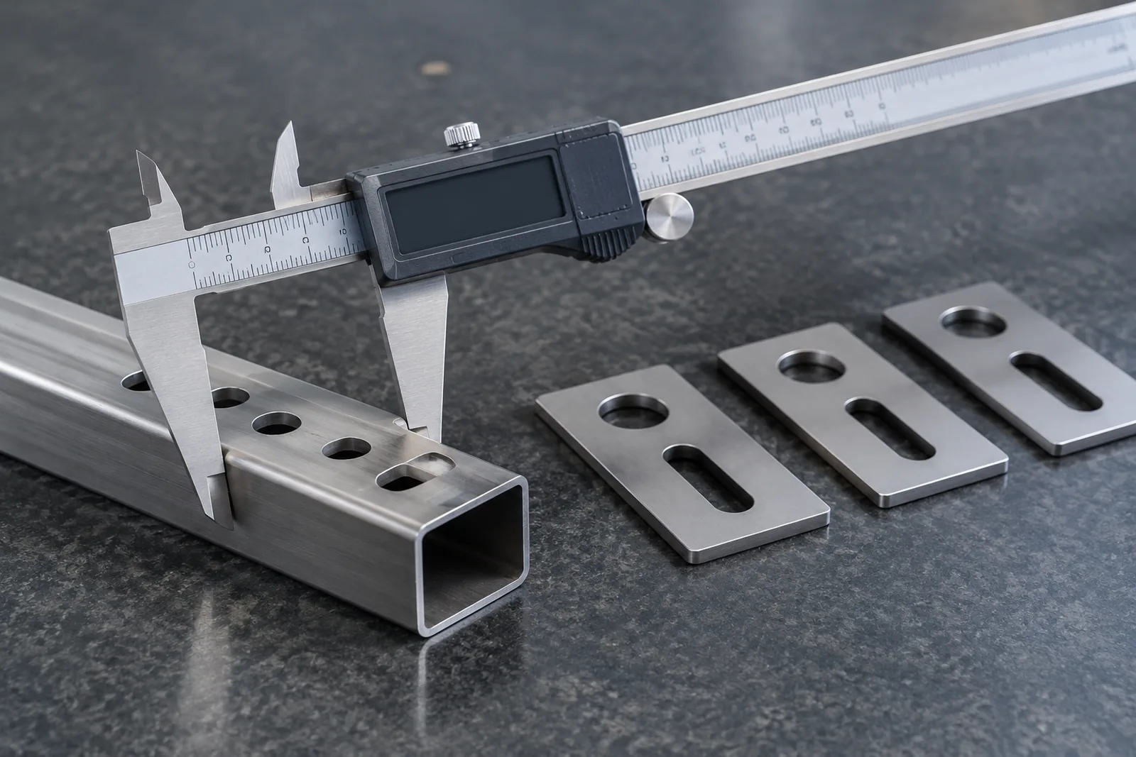
Hole pitch checked with a digital caliper on a laser-cut tube before release.
Sheet vs Tube: Where the Tolerances Differ
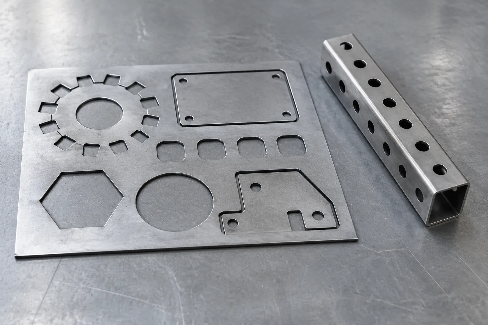
Flat sheet and tube are both cut on fiber laser, but the geometry changes what is achievable. A flat cut is a straight kerf through a constant section; a tube cut is a 3D path across a curved surface, which is why the minimum hole rule is stricter on tube.
| Parameter | Sheet (2D fiber laser) | Tube (3D fiber laser) |
|---|---|---|
| Standard cut tolerance | ±0.1 mm | ±0.1 mm |
| Minimum hole diameter | Equal to material thickness | 1.2 × material thickness |
| Minimum slot width | Equal to material thickness | Equal to material thickness |
| Compound / bevel cuts | Not applicable | ±0.1 – 0.2 mm |
| Working envelope | Sheet up to 6,000 × 2,500 mm | Ø10 – 160 mm round; 10×10 to 160×160 mm square / rectangular; length up to 6,000 mm |
| Wall / thickness range | Confirmed per material at DFM | 0.5 – 20 mm (subject to material) |
| Datum that works | Sheet edge or a cut edge pair | Tube end face — never a floating centreline |
If your drawing is a hybrid — laser-cut sheet brackets welded to laser-cut tube — spec each component against its own column. Applying the sheet minimum-hole rule to a tube hole pattern is the single most common DFM comment our engineers send back.
How Material and Thickness Affect Tolerance
Mild steel and stainless steel hold tighter tolerances than aluminum and copper because they expand less under the same heat input. The alloy decides how much the cut edge moves after the beam passes; the wall thickness decides how much the section distorts.
| Material | Practical standard tolerance | Notes |
|---|---|---|
| Mild steel / carbon steel | ±0.1 mm | Baseline; best stability |
| Stainless steel (304 / 316 / 430) | ±0.1 mm | Holds tight, low thermal distortion |
| Aluminum (6061 / 6063) | ±0.15 mm | Higher thermal expansion; ±0.15 mm is the practical standard |
| Copper / reflective alloys | Contact us | Reflective materials require process review |
Thickness is the second variable. Our tube cells run walls from 0.5 mm to 20 mm, and the tolerance bands above hold across that range subject to material. What changes with thickness is not the machine’s accuracy but the part’s stiffness: a thin wall deflects while it is being cut, so the practical result drifts even though the positioning is unchanged.
Very thin walls, deep narrow slots and long unsupported spans are where we flag tolerance during DFM rather than after the first article. That is a geometry conversation, not a price negotiation.
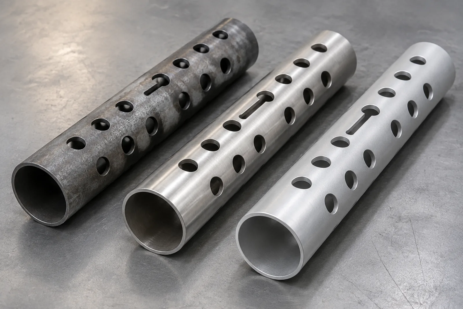
Carbon steel, stainless and aluminum tube samples side by side — the same cut geometry, three different edge conditions.
Writing Drawings for Accurate Quotes
Most quote delays and first-article rejections come from the drawing, not the machine. Four habits remove almost all of it.
1. OD and wall, separately
“Tube size” is not a dimension. Give outside diameter and wall thickness as two separate values — 1.5 mm and 2 mm walls behave very differently at the same OD.
2. Mark only what matters
Flag the dimensions that control fit — mating hole pitch, cut length that sets assembly stack — and let the rest sit at general tolerance. A drawing where everything is critical reads as nothing being critical.
3. Dimension holes from the tube end
Use a fixed datum — the tube end face — not a floating reference or an accumulated chain. It matches how the part is actually located in the fixture.
4. STEP plus DXF for compound angles
A 2D view cannot fully describe a compound angle cut. Send the 3D STEP alongside the 2D DXF so the cut path can be simulated before quoting.
Where teams over-specify (and pay for it)
A tolerance callout only earns its cost when something actually depends on it. Two versions of the same bracket:
Over-specified
±0.05 mm on every dimension
±0.05 mm on a decorative logo cut-out
Hole pitch chained through four intermediate features
Wall thickness shown as one combined “tube 40×2” note
2D drawing only, compound mitre described in a note
Right-sized
General ±0.2 mm title-block tolerance
Mating hole pitch held to ±0.1 mm, flagged
Holes dimensioned from the tube end face
Ø40 OD and 2 mm wall called out separately
STEP file supplied for the mitre; DXF for the flat pattern
Hold the ±0.1 mm band where parts mate, and leave everything else at general tolerance. If a feature genuinely needs tighter than ±0.1 mm, say so and expect a secondary operation — we publish ±0.01 mm on thin-gauge sheet where the application justifies it, and we will tell you when it does not.
Frequently Asked Questions — Laser Cutting Tolerances
What is the standard tolerance for laser cutting?
Standard cut-to-length and profile tolerance is ±0.1 mm, with positioning accuracy of ±0.05 mm. For compound angle cuts on tube, ±0.1–0.2 mm is typical.
Does material affect laser cutting tolerance?
Yes. Mild steel and stainless steel hold ±0.1 mm consistently. Aluminum has higher thermal expansion, so ±0.15 mm is a more practical standard for aluminum tube. Copper and reflective alloys need a process review before we quote a tolerance.
What is the minimum hole size you can laser cut?
On tube, minimum hole diameter is 1.2 × material thickness; on sheet, equal to material thickness. Minimum slot width equals material thickness in both cases. Our engineers confirm feature geometry against your material spec during DFM review.
What tube sizes can you cut?
We cut round, square, rectangular and custom-profile tubes from Ø10 mm to Ø160 mm, up to 6,000 mm in length, with wall thickness from 0.5 mm to 20 mm subject to material.
How should I dimension hole patterns on tube?
Dimension holes from the tube end face — a fixed datum — not from a floating reference. For compound angle cuts, supply a 3D STEP file alongside the 2D DXF so the cut geometry can be simulated.
How do I get an accurate quote?
Send your drawing or specification with material, wall thickness and quantities. Our engineering team reviews the tolerances against material and geometry, returns DFM feedback, and issues a quotation within 24 hours.
Send Us Your Drawing or Specification
Our engineering team will review your tolerances and feature geometry, confirm what the process can hold, and provide DFM feedback plus a quotation within 24 hours.
Email: market@conwhole.com · WhatsApp: +86 180 6900 0612 · Response within 2 business hours